
Project Description
Project name: RGB Music Box
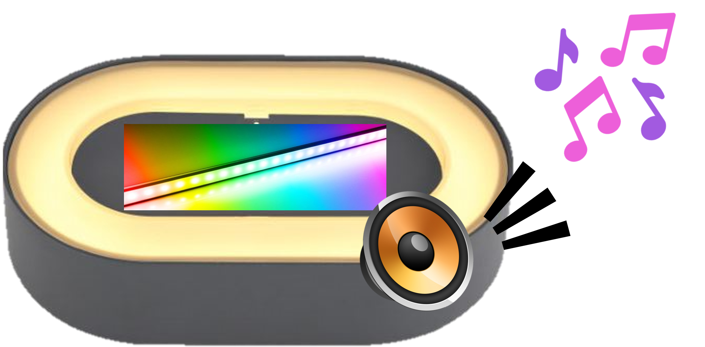
By a touch of your finger, the RGB Music Box will play calming music on loop with sound-reactive RGB LED strips. The touch sensor starts and stops the music, with when the music starts playing, the microphone sound sensor then senses the music and the LED strip reacts to the beats of the music, lighting them up as it plays.
The main features that the RGB Music Box will offer are:
- Start / Stop enabled touch sensor
- .mp3 music player through speaker
- sound-reactive rainbow LED light-up feature
Concept Design
The idea of the RGB Music Box is inspired from portable boomboxes that plays music. In addition, it incorporates RGB lights to add some asthetic looks to it. This gives off a vibe of a portable DJ for parties or relaxation.
The idea in mind was for it to play a soundtrack of a famous youtube podcast, Trash Taste. As the music is playing from the speaker. The sound sensor beside the speaker would pick up the noise level from the speaker and propt the led to light up based on its beat. The music could start and stop based on the user's wants with a touch of his finger.
The concept design in mind is a speaker that is shaped as a pill to follow the design of bluetooth speakers that houses the components inside. The speaker will be incorporated inside, hidden from the user's sight. The LED strip will be behind a translucent pane to spread the light on a bigger area.
Circuit Diagram
In order to build this, we would need all the necessary circuit components listed down below.
Components needed:
- Arduino Uno
- Digital Touch Sensor Module
- Microphone Sound Sensor Module
- DFPlayer Mini
- MicroSD Card
- Speaker 1W 8Ω Buzzer Loud Piezo Arduino PIC
- WS2812B RGB LED Strip(10 Neopixels)
- jumper wires(male-to-male & male-to-female)
The circuit diagram shows how to connect all the components together.
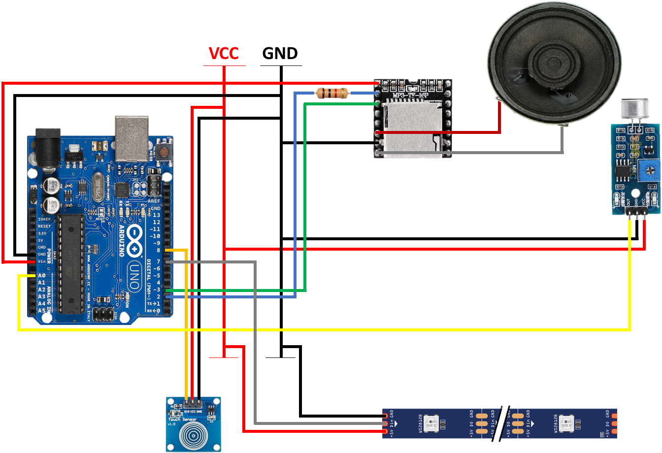
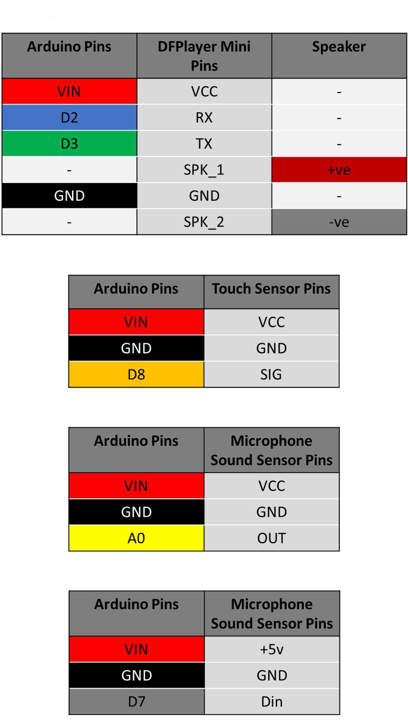
The tables below shows the pins used for each component module and which pins are used for each module for an easier depiction of the circuit diagram
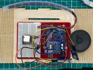
With all the connected pins and components, it will give us something like this.
Code
Before running the code, we would need to install the necessary libraries to run it.
Libraries needed:
- DFRobotPlayerMini by DFRobot
- FastLED by Daniel Garcia
This is the code that will be uploaded into the Arduino Uno to run the whole circuit.
Within this section of the Code, the purpose of each portion of the code will be explained further.
In order for the Arduino Uno to communicate with the DFPlayer Mini, it uses this code for pins 2 and 3 of the Arduino Uno to transmit and receive data to the TX and RX pins of the DFPlayer Mini.
The Arduino Uno initiates communication with the DFPlayer Mini, once communication with it is established, it will print "OK" on the serial monitor and set volume to the maximum level. If communication failed, it would print "Connecting to DFPlayer Mini failed!" on the serial monitor and requires troubleshooting.
The microphone sound sensor will detect the noise level from the speaker and convert that energy to the neopixel LED strips. For each noise at a certain level is detected by the microphone sound sensor, it will turn the LEDs on and clear them when no noise is detected. It also calls the rainbow LED wave function that will be shown later on in this section.
The touch sensor with debounce will toggle between "Start" and "Stop" state upon last touch state. When it is in the "Start" state, it will play audio 0001.mp3 (Trash Taste soundtrack) on loop, allowing the microphone sound sensor to detect its noise level and have the LED react base on its beat. When it is in the "Stop" state, it will play audio 0002.mp3 (silence). This will act as an override so as to stop the audio 0001.mp3 from playing.
This function is used to create the rainbow wave effect for the LED strip.
Hardware
Once the code was settled, all that was left was to make the casing for the final product.
Materials needed:
- 1x 3mm Plywood Sheet
- 1x 3mm Black Acrylic Sheet
- 1x 3mm Matte/Frosted Clear Acrylic Sheet
To start off, the final design is made as a model in Fusion360.
Fusion360 project model:
After that, I took the sketch of the final design's model, added in the "box joint" & "living hinge" and saved it as a DXF file to be laser cutted.
Fusion360 project model flat:
Fusion360 sketch:
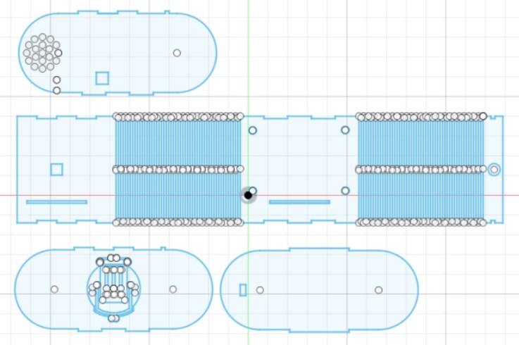
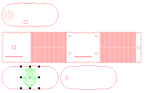
Once the design is done, the sketch is saved as a .DXF file and brought to CorelDRAW to set its laser cutting parameters. The red-highlited sketches are cut-though items while the green-highlighted sketches are engraved items which is used for design purposes.
DXF file in CorelDRAW:
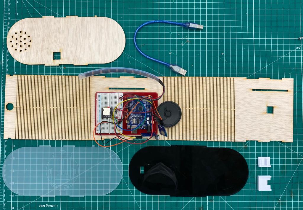
laser cut materials:
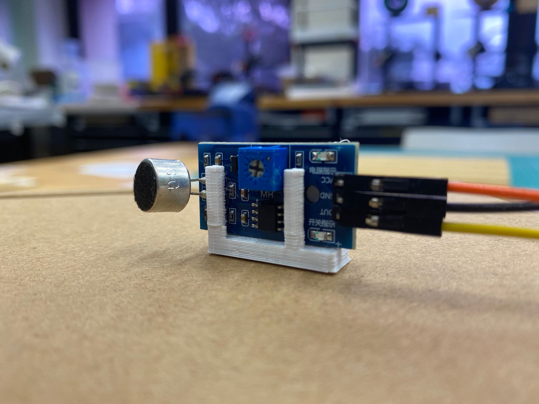
Beside laser cutting the outter cover, a holder to hold the components such as the microphone sound sensor and touch sensor are needed to be made so as to hold them in a proper place without damaging the component.
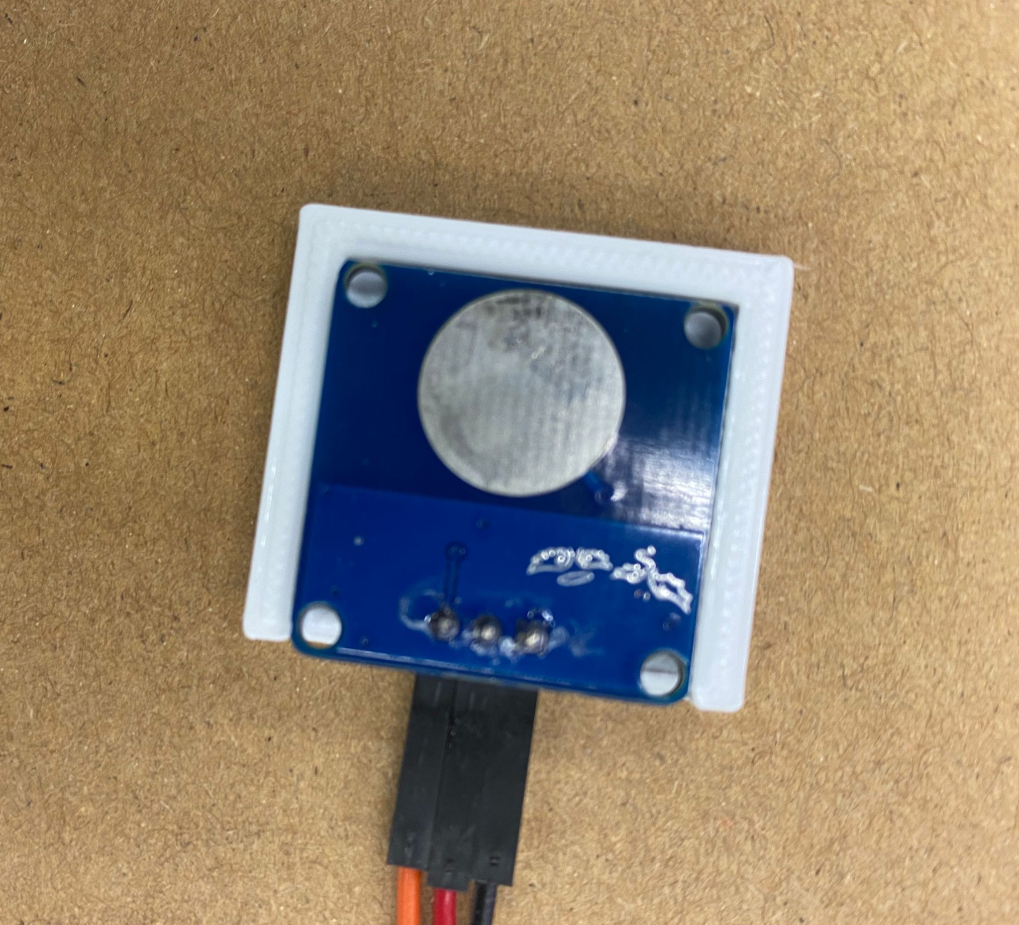
microphone sound sensor holder:
touch sensor holder:
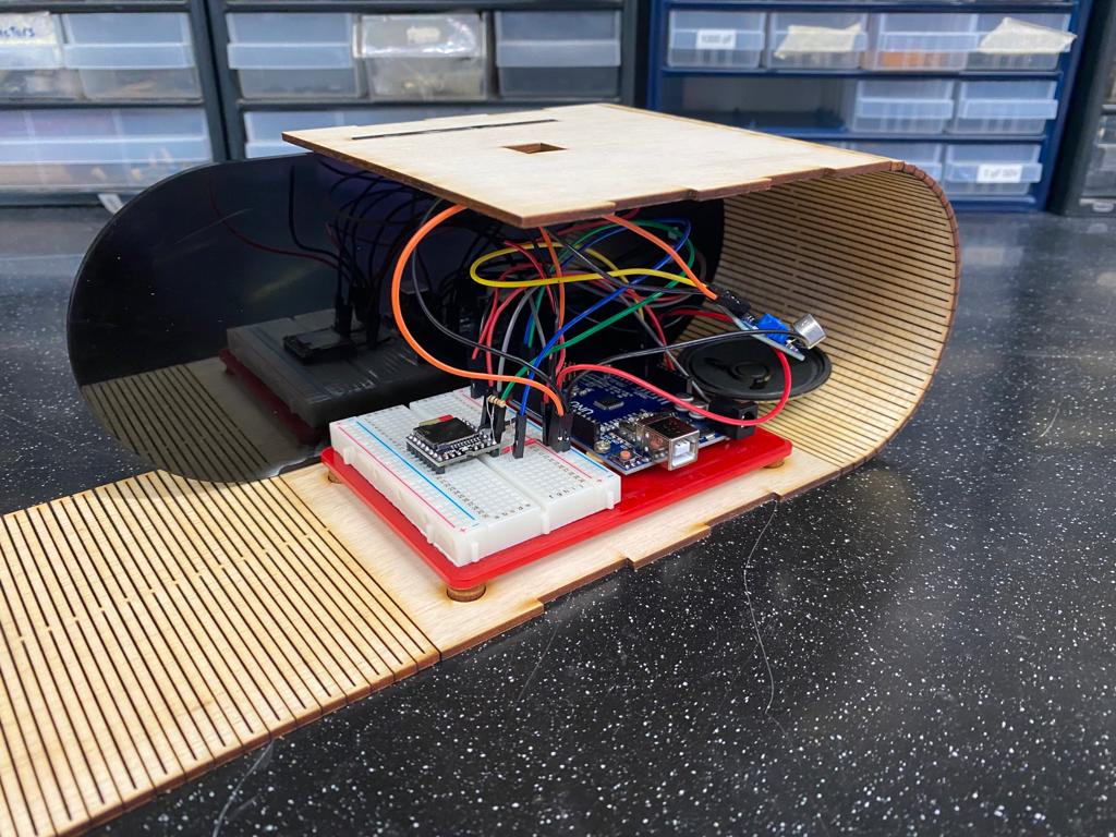
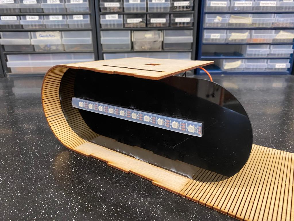
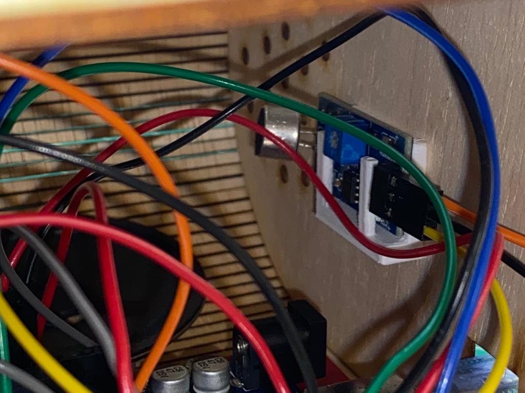
With all the materials in hand, we can assemble all the pieces. Firstly, we place the component board that houses the Arduino Uno and breadboard onto the hole slot of the large wooden body. Place the black acrylic piece into the middle slot. Secure it with super glue to add extra sturdiness to it. Then on the front side, the LED strip is glued to the front area of the black acrylic piece. the rubber protector of the LED strip is attached to the acrylic using super glue. The purpose of this black acrylic is to hold the LED in place and hide all the circuitry from being soon from the front area.
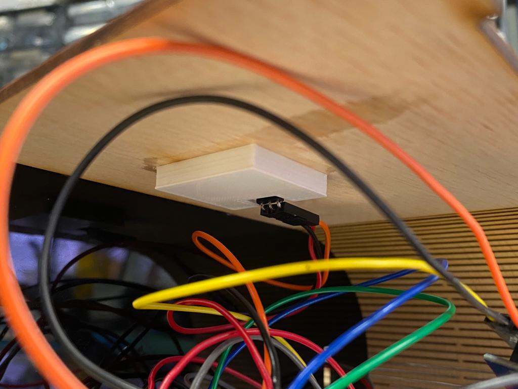
We attach the touch sensor holder onto the box shaped hole of the large wooden body via super glue. This will help to hold the touch sensor in place located on the top of the music box. After the glue has dried, we rap the long top area around and lock it in place into the black acrylic slot.
Next step requires attaching the microphone sound sensor holder onto the back wooden piece. The location of the holder should be located near to the speaker for optimal usage. It is also important to take note of the hole placement for the Arduino Uno so as to allow the wire to connect to the Arduino Uno with ease. We then attach the back wooden piece to the wooden body and utilise super glue for extra sturdiness.
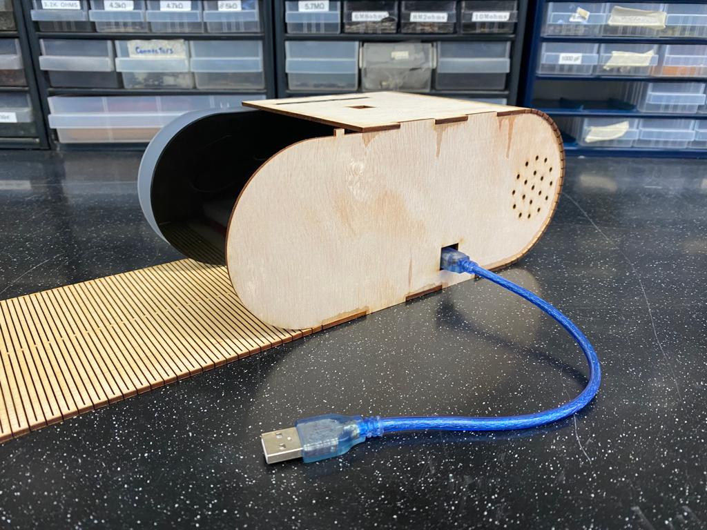
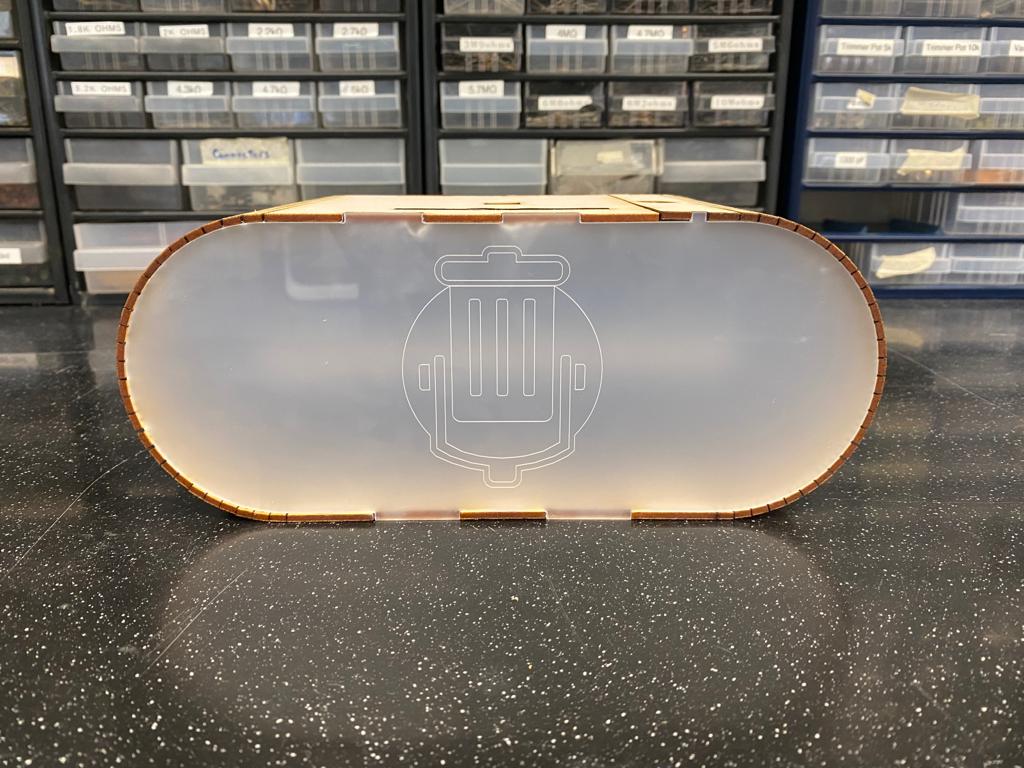
Lastly, we apply the front matte/frosted clear acrylic piece in the front with the design facing outwards. The reason for using matt/frosted clear acrylic was to help disperse the light from the LED strip over a larger area.
Fabrication Techniques
Throughout this process, I have used various fabrication techniques to build this product. The techniques used are as follows.
Techniques used:
- Arduino coding
- Fusion360
- Soldering
- 3D Printing
- Laser Cutting
Bill of Materials
WIth the final product finished, we need to total up the cost to produce this.
With materials such as the plywood and acrylic sheets big enough to produce more than one piece of the project along with components of the circuit such as the sensor modules being bought in bulk, makes this product scalable and less costly to reporduce.
| Material | Cost |
|---|---|
| Arduino Uno | ≈$28 |
| Touch Sensor | ≈$2 |
| Microphone Sound Sensor | ≈$2 |
| DFPlayer Mini | ≈$4 |
| Speaker | ≈$1 |
| LED Strip | ≈$18 |
| Plywood Sheet | ≈$15 |
| Black Acrylic Sheet | ≈$12 |
| Matte/Frosted Clear Acrylic Sheet | ≈$12 |
| Total | ≈$94 |
Final Product
This is the final result of the RGB Music Box.
Additional Resources
PowerPoint Slide: